| Tank Weighing SWB505 MultiMount™ weigh modules offer rugged construction and many features for easy installation and accurate and reliable tank weighing. Standard lift-off bolt copes with ipping forces while vertical safety down-stop provides additional safety. |
 |
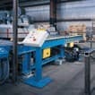 |
Conveyors and Mixers Weigh modules are also designed for dynamic-loading applications such as conveyors, mixers and blenders. SWB505 MultiMount ™provides 360° checking for ease of installation and maximum safety. The rocker pin restores the top plate to its ideal position to maintain accurate, repeatable weight. |
|
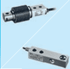
Load Cell Load cells have a rocker pin design that automatically aligns load forces for accurate weighing. These hermetically sealed load cells are rated IP68 and can be used in all environments. The load cells are easy to inspect or replace |
 |
 |
Stabilizers Up to two optional stabilizers can be applied to each weigh module to stabilize a scale subject to heavy vibration, high torque, or in-motion weighing. With stabilizers installed, thermal expansion is still possible, guaranteeing the best weighing performance. |
SWB505 MultiMountTM Right the First Time
SWB505 MultiMount™ features ensure correct scale system installation, right from the start. Weigh modules do not compromise on safety – all safety features are built-in. The rocker pin design provides the highest level of weighing accuracy. Service features, including SafeLock™ provide easy and trouble free installation.
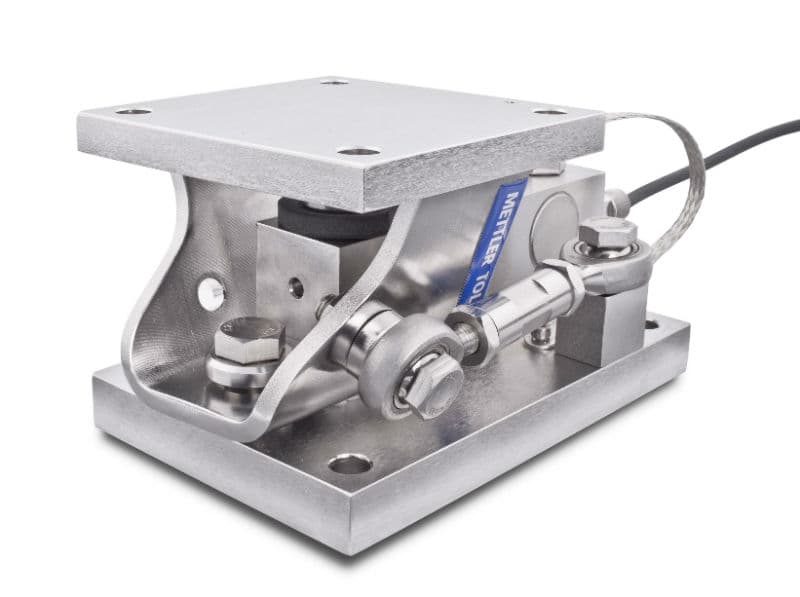 |
Features: • Integrated lift-off protection
|
| Weigh Module | unit of
measure |
Specification | |||||||||||||||
| Model No. | SWB505 MultiMount ™ | ||||||||||||||||
| Size | 1 | 2 | 3 | ||||||||||||||
| Rated Capacity | kg (lb,
nominal) |
5
(11) |
10
(22) |
20
(44) |
30
(66) |
50
(110) |
100
(220) |
200
(440) |
300
(660) |
110
(250) |
220
(500) |
550
(1250) |
1100
(2500) |
2200
(5000) |
4400
(10000) |
||
| Max. Rated Forces 1) | |||||||||||||||||
| Max. Compressive Force, Rated | kN (lb) | 0.05
(11) |
0.1
(22) |
0.2
(44) |
0.3
(66) |
0.5
(110) |
1
(220) |
2
(440) |
3
(660) |
1.1
(250) |
2.2
(500) |
5.4
(1250) |
10.8
(2500) |
21.6
(5000) |
43.2
(10000) |
||
| Max. Horizontal Force, Rated | transverse | kN (lb) | 4.5 (1010) | 7.5 (1685) | 15
(3370) |
||||||||||||
| longitudinal | |||||||||||||||||
| Max. Uplift Force, Rated | kN (lb) | 5.5 (1230) | 16 (3600) | 22.2
(5000) |
|||||||||||||
| Max. horizontal force (longitudinal)
per stabilizer option, Rated 7) |
kN (lb) | 1.5 (675) | 5 (1120) | 7.4
(1660) |
|||||||||||||
| Max. Yield Forces 2) 4) | |||||||||||||||||
| Max. Compressiv Force, Yield | kN (lb) | 0.074
(16.5) |
0.15
(33) |
0.29
(66) |
0.44
(99) |
0.74
(165) |
1.47
(330) |
2.94
(660) |
4.4
(990) |
1.62
(375) |
3.2
(750) |
8.1
(1875) |
16.2
(3750) |
23.3
(5120) |
50
(11200) |
||
| Max. Horizontal Force, Yield | transverse | kN (lb) | 6.6 (1480) | 9.8 (2200) | 22
(4950) |
||||||||||||
| longitudinal | |||||||||||||||||
| Max. Uplift Force, Yield | kN (lb) | 7.7 (1730) | 22 (4950) | 34
(7640) |
|||||||||||||
| Max. Ultimate Forces 3) 4) | |||||||||||||||||
| Max. Compressiv Force, Ultimate 5) | kN (lb) | 65 (14600) | 90 (20000) | 150
(33000) |
|||||||||||||
| Max. Horizontal Force, Ultimate | transverse | kN (lb) | 17 (3800) | 42 (9400) | 48
(10750) |
||||||||||||
| longitudinal | |||||||||||||||||
| Max. Uplift Force, Ultimate | kN (lb) | 22 (4590) | 50 (11200) | 55
(12350) |
|||||||||||||
| Restoring Force | %A.L./mm
(../in) 6) |
7.4 (190) | 4.4 (111) | 5.5
(140) |
|||||||||||||
| Max. top plate travel | transverse | ± mm (in) | 2.5 (0.10) | 3 (0.12) | 3.5
(0.14) |
||||||||||||
| longitudinal 8) | |||||||||||||||||
| Weight (including load cell), nominal | kg (lb) | 4
(8.8) |
6.6
(14.5) |
7
(15.4) |
15.4
(34) |
||||||||||||
| Material | carbon steel / 304 stainless steel / 316 stainless steel | ||||||||||||||||
| Finish | Zinc Plated / Electropolished / Electropolished | ||||||||||||||||
1) The weigh module is rated for these forces in normal operation, a Factor of Safety has been applied by Mettler Toledo.
2)arWning: if loaded statically one time in excess of these forces, the weigh module may yield and need replacing. The Max. Yield Forces do not consider fatigue/cyclic loading and should be approached only in exceptional circumstances.
3)arWning: if loaded statically one time in excess of these forces, the weigh module may break with potential for serious injury and/or property damage.
4)arWning: apply a Factor of Safety appropriate to the application.
5) The top plate will travel downwards by 5 mm (0.2 inches) before the down-stop engages and this ultimate force can be developed.
6) % of Applied Load (A.L.) per mm (in) displacement of the top plate (transverse & longitudinal).
7) 1 or 2 per weigh module. Max permissible longitudinal force per stabilizer.
8) 0 with Stabilizer.
SWB505 MultiMount ™ Specifications – Load Cell
| Load Cell | unit of
measure |
Specification | ||||||||||||||
|
Item No. |
0.03% | 30129791 | ||||||||||||||
| 0.05% | 71209934 | |||||||||||||||
| C3 / III s n:3 /
III M n:5 |
71209642 | 71201556 | 71201557 | 71201558 | 71201559 | 71201560 | ||||||||||
| C3 / III M n:5 | 30091046 | 30091050 | 30091054 | 30039033 | 30094400 | |||||||||||
| C6 | 30212721 | 30212722 | 30212723 | 30212724 | 30212725 | |||||||||||
| C6 / III M n:10 | 30091047 | 30091051 | 30091055 | 30039034 | 30094401 | |||||||||||
| Model No. | MTB | 0745A | ||||||||||||||
| Rated Capacity (R.C.) | kg (lb,
nominal) |
5
(11) |
10
(22) |
20
(44) |
30
(66) |
50
(110) |
100
(220) |
200
(441) |
300
(661) |
110
(250) |
220
(500) |
550
(1250) |
1100
(2500) |
2200
(5000) |
4400
(10000) |
|
|
Rated Output |
mV/V
@R.C.-kg |
2 ± 0.1% | 0.970 ±
0.2% |
1.940 ± 0.1% | ||||||||||||
| mV/V
@R.C.-lb |
– | 1.000 ±
0.2% |
2.000 ± 0.1% | |||||||||||||
| Combined Error 9) 10) | %R.C. | C3: ≤ 0.018 / C6: ≤ 0.012 | ≤ 0.03 | C3: ≤ 0.018 / C6: ≤ 0.012 | ||||||||||||
|
Temperature Effect on |
Min. Dead load
Output |
%R.C./°C
(../°F) |
C3: ≤ 0.001 (0.0006) / C6: ≤ 0.001 (0.0006) | ≤ 0.0027
(0.0015) |
C3: ≤ 0.0013 (0.0007) /
C6: ≤ 0.0013 (0.0007) |
|||||||||||
| Sensitivity 10) | %A.L./°C
(../°F) |
C3: ≤ 0.001 (0.0006) / C6: ≤ 0.0005 (0.0003) | ≤ 0.0014
(0.0008) |
C3: ≤ 0.001 (0.0006) /
C6: ≤ 0.0005 (0.0003) |
||||||||||||
| Temperature Range | Compensated |
°C (°F) |
-10 ~ +40 (+14 ~ +104) | -10 to +40 (+14 to +104) | ||||||||||||
| Operating | -40 ~ +65 (-40 ~ +150) | -40 to +65 (-40 to +150) | ||||||||||||||
| Safe Storage | -40 ~ +80 (-40 ~ +176) | -40 to +80 (-40 to +176) | ||||||||||||||
| OIML /
European Approval 11) |
Class |
– |
C3 | C6 | C3 / C6 |
– |
C3 / C6 | |||||||||
| nmax | 3000 | 6000 | 3000 / 6000 | 3000 / 6000 | ||||||||||||
| Y | 12000 | 11000 | ||||||||||||||
|
NTEP Approval 11) |
Class | III S / III M |
– |
III M / III M | ||||||||||||
| nmax | 3000 / 5000 | 5000 / 10000 | ||||||||||||||
| Vmin | kg (lb) | R.C./12000 | 0.022 | 0.056 | 0.114
(0.25) |
0.227
(0.50) |
0.454
(1.0) |
|||||||||
| ATEX
Approval 11) Rating |
II 2 G Ex ib IIC T4 / II 2 D ibD 21 IP6X T135°C | II 2 G Ex ia IIC T4 Gb / II 2 D Ex ia IIIC T100°C Db | ||||||||||||||
| II 3 G Ex nA II T4 / II 3 G Ex nL IIC T4 / II 3 D Ex tD A22 IP6X T135°C | II 3 G Ex ic IIC T4 Gc / II 3 G Ex nA IIC T4 Gc /
II 3 D Ex tc IIIC T100°C Dc |
|||||||||||||||
|
IECEx Approval 11) |
Number | IECEx DEK 16.0031X | IECEx DEK 15.0017 | |||||||||||||
| Rating | Ex ib IIC T4 Gb / Ex ib IIIC T135°C Db / Ex ic IIC T4 Gc / Ex nA IIC T4 Gc /
Ex tc IIIC T135°C Dc |
Ex ia IIC T4 Gb / Ex ia IIIC T100°C DbEx ic IIC T4 Gc /
Ex nA IIC T4 Gc / Ex tc IIIC T100°C Dc |
||||||||||||||
| Entity
Parameters |
Ui = 25V, li = 600mA, Pi = 1.25W, Ci = 0.2nF/m, Li = 1µH/m / Un = 25V | Ui = 25V, Ii = 600mA, Pi =1.25W, Ci = 5nF, Li = 30µH /
Un = 25V, Ci = 5 nF |
||||||||||||||
| Factory Mutual Ap- proval 11) | Rating, USA | IS / I, II, III / 1 / ABCDEFG / T4 | IS / I, II, III / 1 / ABCDEFG / T4 | |||||||||||||
| NI / I / 2 / ABCD / T6 / S / II, III / 2 / FG / T6 | NI / I / 2 / ABCD / T6 / S / II, III / 2 / FG / T6 | |||||||||||||||
| Rating, Canada | IS / I, II, III / 1 / ABCDEFG /T4 | IS / I, II, III / 1 / ABCDEFG /T4 | ||||||||||||||
| NI / I / 2 / ABCD / T6 / DIP / II, III / 2 / FG / T6 | NI / I / 2 / ABCD / T6 / DIP / II, III / 2 / FG / T6 | |||||||||||||||
| Excitation Voltage | Recommended | V AC/DC | 5~15 | C3: 5~15 / C6: 5~10 | ||||||||||||
| Max. | 20 | 15 | ||||||||||||||
| Terminal Resistance | Excitation | Ω | ≥ 383 | 384 ± 10 | ||||||||||||
| Output | 350 ± 1 | 350 ± 2 | ||||||||||||||
| Material Spring Element | stainless steel | stainless steel | ||||||||||||||
|
Protection |
Type | welded | welded | |||||||||||||
| IP Rating | IP 68 , IP69K | IP 68 , IP69K | ||||||||||||||
| NEMA Rating | NEMA 6/6P | NEMA 6/6P | ||||||||||||||
| Weight, nominal | kg (lb) | 0.6 (1.3) | 0.9 (2) | 1.3
(2.9) |
2
(4.4) |
|||||||||||
| Cable Length | Lenght | m (ft) | 3 (9.8) / 5 (16.4) | PU: 2 (6.6), 3 (9.8), 5 (16.4), 10 (32.8) /
FEP: 3 (9.8), 5 (16.4), 10 (32.8) |
||||||||||||
| Diameter | mm (in) | 5.8 (0.23) | PU: 5.2 (0.2) / FEP: 5.3 (0.21) | |||||||||||||
9) Error due to the combined effect of non-linearity and hysteresis.
10)yTpical values only. The sum of errors due to Combined Error and Temperature Effect on Sensitivity comply with the requirements of OIML R60 and NIST HB44.
11) See certificate for complete information.
|
Size |
Capacity |
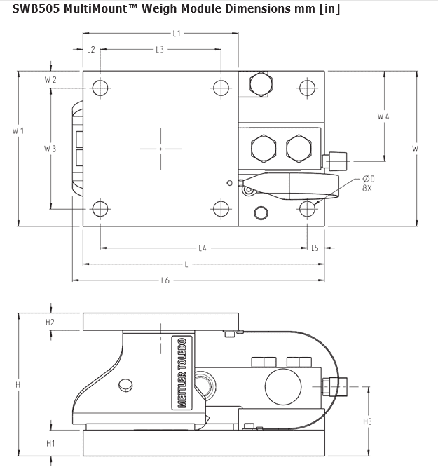
Locations and Dimensions | ||||||||||||||||
| D | H | H1 | H2 | H3 | L | L1 | L2 | L3 | L4 | L5 | L6 | W | W1 | W2 | W3 | W4 | ||
| 1 | 5 kg – 300 kg
(11 lb – 600 lb) |
10
(0.4) |
83
(3.3) |
12.7
(0.50) |
8
(0.3) |
41.0
(1.61) |
165
(6.5) |
102
(4.0) |
10
(0.4) |
82
(3.2) |
145
(5.7) |
10
(0.4) |
– | 102
(4.0) |
102
(4.0) |
10
(0.4) |
82
(3.2) |
60.0
(2.36) |
|
2 |
110 kg – 1.1 t
(250 lb – 2.5 klb) |
11.2 (0.44) |
105.2 (4.14) |
19.1 (0.75) |
12.7 (0.50) |
50.9
(2.00) |
177.9 (7.00) |
114.4 (4.50) |
12.7 (0.50) |
89.0 (3.5) |
152.4 (6.00) |
12.7 (0.50) |
185.6 (7.31) |
114.4 (4.50) |
114.4 (4.50) |
12.7 (0.50) |
89.0 (3.5) |
66.6
(2.62) |
| 2.2 t (5 klb) | 51.3
(2.02) |
69.7
(2.74) |
||||||||||||||||
| 3 | 4.4 t (10 klb) | 17.5
(0.69) |
136.6
(5.38) |
25.4
(1.00) |
19.1
(0.75) |
70.3
(2.77) |
235.0
(9.25) |
152.4
(6.00) |
25.4
(1.00) |
101.6
(4.00) |
184.2
(7.25) |
25.4
(1.00) |
– | 152.4
(6.00) |
152.4
(6.00) |
25.4
(1.00) |
101.6
(4.00) |
91.7
(3.61) |
Sản phẩm cùng loại
-
-
Hãng Mettler Toledo, Hãng Mettler Toledo
Cảm biến lực (Load cells) SLB415 – 220kg
Cảm biến tải trọng dạng thanh một đầu có thể được sử dụng để chuyển đổi bất kỳ cấu trúc nào thành cân.
Cảm biến tải trọng dạng thanh SLB415 có lỗ đặt tải mù để sử dụng với rocker pin, sự lựa chọn tốt nhất cho các ứng dụng có độ chính xác cao.
SKU: n/a -
Hãng Mettler Toledo, Hãng Mettler Toledo
Cảm biến lực (Load cells) SLB415 – 110kg
Cảm biến tải trọng dạng thanh một đầu có thể được sử dụng để chuyển đổi bất kỳ cấu trúc nào thành cân.
Cảm biến tải trọng dạng thanh SLB415 có lỗ đặt tải mù để sử dụng với rocker pin, sự lựa chọn tốt nhất cho các ứng dụng có độ chính xác cao.
SKU: n/a